Description
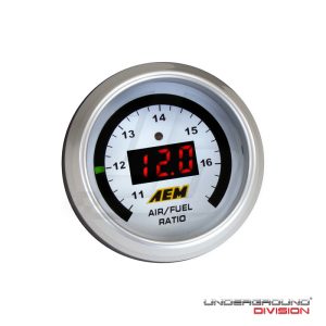
AEM WIDEBAND FAILSAFE GAUGE
A WIDEBAND AND BOOST/VACUUM GAUGE COMBO THAT CAN SAVE YOUR ENGINE IF IT RUNS LEAN
The Wideband FAILSAFE Gauge is a Universal Exhaust Gas Oxygen (UEGO—“you-way-go”) controller with an internal boost sensor, an internal data logger and a full color Organic Light Emitting Diode (OLED) display. It includes technology to activate a failsafe strategy in the event AFR falls outside of a user-defined operating window. If the AFR falls outside of the set operating window, the Wideband FAILSAFE Gauge triggers a user defined output function that can save an engine from catastrophic damage.
WIDEBAND FAILSAFE GAUGE TECHNICAL FEATURES:
Displays both boost or vacuum and AFR or Lambda simultaneously on the same gauge
Internal boost sensor
Bosch Wideband UEGO sensor and weld-in bung included
On-Board 3+ hour Datalogging capability at 20hz per parameter (AFR/Lambda, Boost/Vacuum and RPM**)
Full color Organic Light Emitting Diode (OLED) Display in center, user selectable feature (boost/vacuum or AFR)
24 three-color sweeping LEDs, user selectable feature (boost/vacuum or AFR)
Intuitive set up software
Dimmer input included
Interchangeable faceplates and bezels (see options, below)
No free air calibration required—ever
Data analysis using AEMdata software
WIDEBAND FAILSAFE GAUGE INSTALLATION FEATURES:
AEMnet compatible (CAN 2.0)
Differential AFR analog output
Differential boost analog output
Configurable RPM input for logging
One low-side driver output (Ground with 1.5 amp max draw)
Positive-lock connectors
Tunable PC-based software with USB connectivity
Time based reset for outputs
WIDEBAND FAILSAFE GAUGE FACEPLATE STYLES:
Kit comes with 6 different faceplates and black and silver bezels.
Black Vacuum only in sweeping LEDs
Black and White AFR in sweeping LEDs
Black and White Vacuum/Boost in sweeping LEDs
Black Lambda in sweeping LEDs
**IMPORTANT INFORMATION REGARDING USING THE RPM INPUT FOR THE WIDEBAND FAILSAFE GAUGE
The AEM Wideband Failsafe Gauge’s (WBFS) engine speed (RPM) input requires a clean square wave tachometer-type signal in order to log engine speed properly.
The voltage of this signal must NOT exceed 16V or go below vehicle ground (zero volts.)
Here are examples of signals that WILL NOT work and could cause damage to the gauge:
- Crank sensors
- Ignition coil primary (positive or negative terminal)
- Injector signals
Here are examples of suggested RPM input configurations:
An MSD GMR Pickup (P/N #8918) connected to: coil primary (inductive or capacitive) or fuel injector*
An aftermarket multi-strike distributor tachometer output (for example: MSD-6AL, Crane Hi-6, etc.)
OEM tachometer signal (0-12V square wave—verification with an oscilloscope recommended)
*Note: Install the GMR Pickup as per MSD instructions; the GMR is generally installed on the “+” side of referenced signals.
If a signal’s waveform is unknown and cannot be verified with an oscilloscope, it’s safest to assume that the signal won’t work and could possibly damage the gauge. In these cases, it is suggested that the MSD GMR Pickup be utilized to pick up off of an ignition coil.


